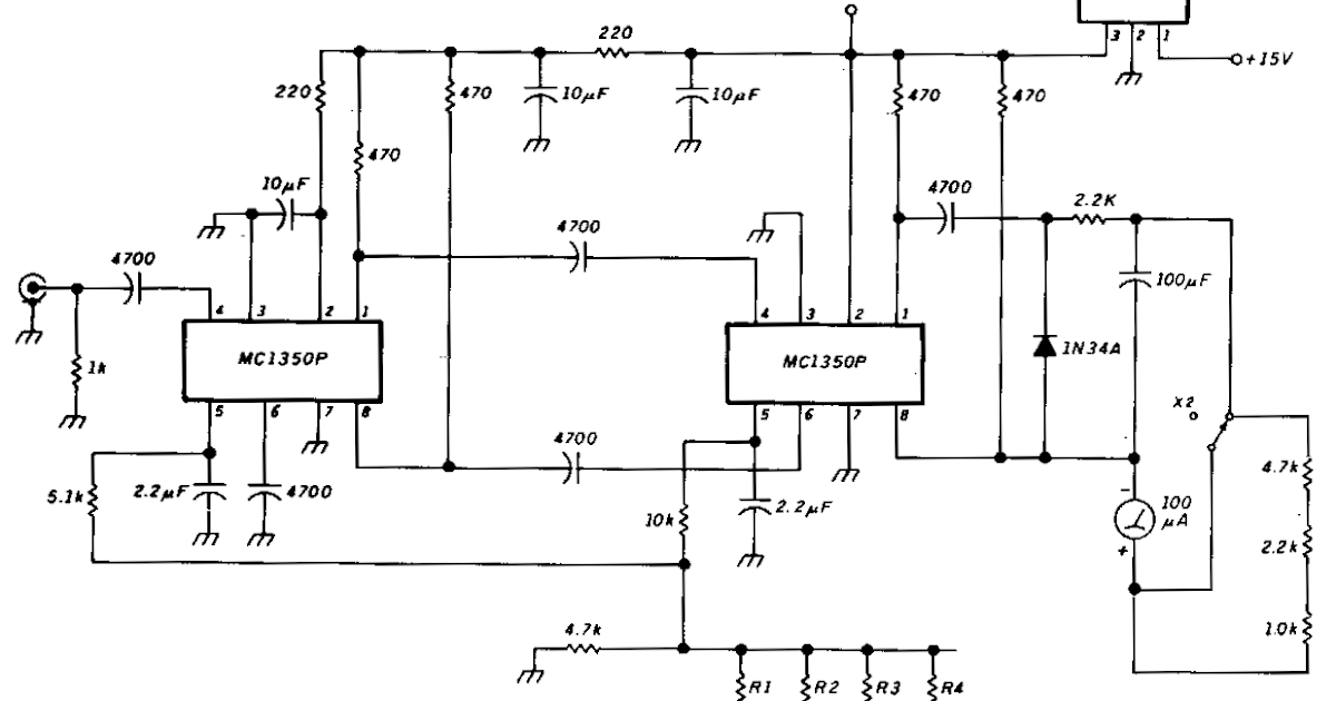
How To Connect A Voltmeter In A Circuit
How to connect a voltmeter in a circuit Voltmeter connected resistance reading Voltmeter wiring diagram. 3 phase digital voltmeter wiring diagram
Measuring voltage with different voltmeters in parallel - influences
Solved: four voltmeters are connected to a circuit as show... Voltmeter parallel placed keystagewiki Voltage dc voltmeter circuit high 1000v make diagram
Circuit voltmeter digital 7107 icl dvm using display segment clock make
Electronic voltmeter working and block diagramVoltmeter dc measured circuits conceptual circuit1 peoi Voltmeter wiring diagram phaseVoltmeter connection with selector switch.
Solved how should you connect a voltmeter to measure theVoltmeter ammeters voltage voltmeters parallel ammeter resistor placed pressbooks libretexts resistors electrical Voltmeter electrical electricalacademiaVoltmeter connect measure voltage resistor solved across answer problem been has.

Electric potential difference
Selector switch voltmeter connectionIf the reading of voltmeter connected in the circuit is 10 v. the Voltmeter circuit potential teachoo ncert pointsSimple circuit diagram of voltmeter.
Measuring voltage with different voltmeters in parallelHow to make a high voltage dc voltmeter (1000v+ !!!) – lab projects bd Voltmeter connectionDigital voltmeter (dvm) circuit using icl-7107.

How is the voltmeter connected into a circuit?
Voltmeter connect circuit21.4 dc voltmeters and ammeters – college physics Circuit connected voltmeters four usual shown diagram voltmeter reading solvedParallel voltmeters voltage different measuring influences finite influence those because each would their other.
.

How is the voltmeter connected into a circuit? - Quora

Measuring voltage with different voltmeters in parallel - influences

If the reading of voltmeter connected in the circuit is 10 V. The

VOLTMETER WIRING DIAGRAM. 3 PHASE DIGITAL VOLTMETER WIRING DIAGRAM

How to make a high voltage DC voltmeter (1000V+ !!!) – Lab Projects BD

Solved How should you connect a voltmeter to measure the | Chegg.com
.jpg)
Electric Potential Difference - Definition, Formula, Unit - Teachoo

21.4 DC Voltmeters and Ammeters – College Physics

Digital Voltmeter (DVM) Circuit Using ICL-7107 - Engineering Projects